How GMR Works
| |  GMR
Overview (02:00) GMR
Overview (02:00)
| “GMR can be considered
one of the first real applications of the promising field of nanotechnology.”
—Nobel Prize Committee, October 2007 What's
Giant in “Giant Magnetoresistance”?
Although the term "giant"
in giant magnetoresistance (GMR) seems incongruous for a nanotechnology device,
it refers to a large change in resistance (typically 10 to 20%) when the devices
are subjected to a magnetic field, compared with a maximum sensitivity of a few
percent for other types of magnetic sensors. Nanotechnology Structure
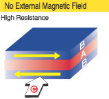
GMR structures are ferromagnetic alloys sandwiched around an ultrathin nonmagnetic
conducting middle layer:

(A) is a conductive, nonmagnetic interlayer. Magnetic moment in alloy
(B) layers face opposite directions due to antiferromagnetic coupling. Resistance
to current (C) is high. The nonmagnetic conducting layer is often copper. Copper
is normally an excellent conductor, but when it is only a few atoms thick, electron
scattering causes copper’s resistance to increase significantly. This resistance
changes depending on the relative orientation of electron spins surrounding the
conducting layer
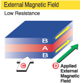
Applying an external magnetic field (D) overcomes antiferromagnetic
coupling, aligning magnetic moments in alloy (B) layers: 
Such exposure changes the device resistance so the structure can be used to
sense an external field. Practical devices are often made of multiple layers of
alternating magnetic and nonmagnetic layers to improve sensitivity. The
Quantum Mechanics of GMR
To understand how GMR works on the atomic level,
consider the following analogies: If a person throws a ball (analogous to a conduction
electron) between two sets of rollers turning the same direction (analogous to
parallel spin-aligned magnetic layers), the ball tends to go through smoothly.
But if the top and bottom rollers turn in opposite directions, the ball tends
to bounce and scatter. Alternatively, the GMR effect may be compared to light
passing through polarizers. When the polarizers are aligned, light passes through;
when their optical axes are rotated with respect to each other, light is blocked. The
resistance of metals depends on the mean free path of their conduction electrons,
which, in GMR devices, depends on the spin orientation. In ferromagnetic materials,
conduction electrons either spin up when their spin is parallel to the magnetic
moment of the ferromagnet, or spin down when they are antiparallel. In nonmagnetic
conductors, there are equal numbers of spin-up and spin-down electrons in all
energy bands. Because of the ferromagnetic exchange interaction, there is a difference
between the number of spin-up and spin-down electrons in the conduction bands.
Quantum mechanics dictates that the probability of an electron being scattered
when it passes into a ferromagnetic conductor depends on the direction of its
spin. In general, electrons with a spin aligned with the majority of spins in
the ferromagnets will travel further without being scattered. In a GMR spintronic
device, the first magnetic layer polarizes the electron spins. The second layer
scatters the spins strongly if its moment is not aligned with the polarizer’s
moment. If the second layer’s moment is aligned, it allows the spins to pass.
The resistance therefore changes depending on whether the moments of the magnetic
layers are parallel (low resistance) or antiparallel (high resistance). Optimal
layer thicknesses enhance magnetic-layer antiparallel coupling, which is necessary
to keep the sensor in the high-resistance state when no field is applied. When
an external field overcomes the antiparallel coupling, the moments in the magnetic
layers align and reduce the resistance. If the layers are not the proper thickness,
however, the coupling mechanism can destroy the GMR effect by causing ferromagnetic
coupling between the magnetic layers. For spin-dependent scattering to be
a significant part of the total resistance, the layers must be thinner (to a magnitude
of several nanometers) than the mean free path of electrons in most spintronic
materials. A typical GMR medical sensor has a conducting layer approximately 3
nm (or one ten-millionth of an inch) thick. For reference, that is less than 10
atomic layers of copper, and less than one ten-thousandth the thickness of a piece
of tissue paper. Spintronic GMR Bridge Sensors
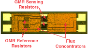
A photomicrograph
of a typical GMR magnetic sensor, also known as a magnetometer is shown below:
 The
thin metal-alloy films are vacuum deposited onto silicon wafers. Other manufacturing
steps include thermal annealing, magnetic annealing, and photolithography. GMR
resistors are generally patterned into serpentine resistors using photolithography.
The serpentine configuration maximizes resistance per unit area. Maximizing resistance
minimizes power consumption when the sensor is sampled. In a typical sensor,
four GMR resistors are configured as a Wheatstone bridge. A bridge configuration
provides an easy-to-use voltage output that is proportional to the magnetic field
applied but insensitive to any variations in the absolute resistance of the GMR
device. Two of the resistors are sensing resistors; the other two are reference
resistors. The reference resistors are covered by a nickel-iron magnetic shield
that measures 0.0004 in. thick. In response to an external magnetic field, the
exposed sensing resistors decrease in electrical resistance while the reference
resistors remain unchanged, causing a voltage at the bridge output. The
shield may also serve as a flux concentrator for the sensing resistors, increasing
the sensitivity of the device and improving its spatial specificity. Because of
the small geometries of spintronic sensors, flux concentration is especially effective
and can increase sensitivity up to a factor of 100. GMR Electrical Characteristics
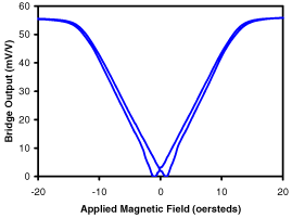
A typical GMR sensor output is shown below:  When
a magnetic field produces no further change in resistance, it is deemed saturated.
The change in resistance from no field to saturation, usually expressed as a percentage
of saturated resistance, is known as magnetoresistance. Hysteresis is the separation
between positive- and negative-going curves. Although this diagram shows
an omnipolar response, meaning it has the same change in resistance for a directionally
positive or directionally negative magnetic field, bipolar
sensors have recently become available. Bipolar sensors maintain an operate point
with the application of a negative (South) magnetic field, and a release point
with the application of a positive (North) magnetic field. The part is ideal for
use with magnetic encoders that have alternating North/South poles. GMR
Sensor Product Configurations
NVE offers a full line of GMR sensors and
related products, including analog, digital,
and rotational GMR sensors.
References and Further Reading
|